
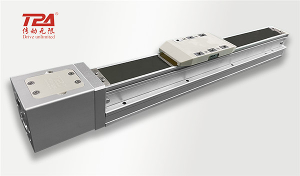
Ball screw type linear actuator mainly consists of ball screw, linear guide, aluminum alloy profile, ball screw support base, coupling, motor, limit sensor, etc.
Ball screw: Ball screw is ideal for converting rotary motion into https://www.tparobot.com linear motion, or linear motion into rotary motion. Ball screw consists of screw, nut and ball. Its function is to convert rotary motion into linear motion, which is a further extension and development of ball screw. Due to its small frictional resistance, ball screw is widely used in various industrial equipment and precision instruments. High precision linear motion can be achieved under high load. However, ball screw does not have the self-locking ability of trapezoidal screw, which needs attention in the process of use.
Linear guide: linear guide, also known as slideway, linear guide, linear slide, for linear reciprocating motion occasions, has a higher load rating than linear bearings, while can bear a certain torque, can be in the case of high load to achieve high precision linear motion, in addition to some lower precision occasions can also be replaced with box linear bearings, but it should be noted that in the torque and load rating capacity In terms of poorer than linear guide.
Module aluminum alloy profile: module aluminum alloy profile sliding table beautiful appearance, reasonable design, good rigidity, reliable performance, low production cost is often used in industrial automation equipment, through finishing assembly into the module rigidity, thermal deformation is small, feeding stability is high, thus ensuring high precision and high stability of operation in automation equipment.
Ball screw support seat: ball screw support seat is a bearing support seat to support the connection between the screw and the motor, the support seat is generally divided into: fixed side and support unit, the fixed side of the support unit is equipped with pre-pressure adjusted angular contact ball bearings. In particular, in the ultra-compact type, the ultra-compact angular contact ball bearing with a contact angle of 45° developed for ultra-compact ball screws is used to achieve stable rotary performance with high rigidity and high precision. Deep groove ball bearings are used in the support unit on the support side. The internal bearing of the support unit is filled with an appropriate amount of lithium soap-based grease and sealed with a special sealing gasket, allowing direct mounting and long-term use. The optimum bearing is adopted considering the balance of rigidity with the ball screw, and the angular contact ball bearing with high rigidity and low torque (contact angle 30°, free combination) is used. Also, the ultra-compact support unit is equipped with an ultra-compact angular contact ball bearing developed for ultra-compact ball screws. This type of bearing has a 45° contact angle, a small ball diameter and a large number of balls, and is an ultra-small angular contact ball bearing with high rigidity and high precision, and can obtain stable slewing performance. The shape of the support unit is available in angular type and round type series, which can be selected according to the application. Small and easy to install, the support unit is designed with a small size that takes into account the space around the installation. At the same time, the pre-pressured bearings can be mounted directly after delivery, reducing assembly time and improving assembly accuracy. Of course, if it is necessary to save cost design, you can also make your own non-standard parts bearing housing, with outsourcing bearing combination into a support unit, batch application is very advantageous in terms of cost.
Coupling: Coupling is used to connect two shafts together to transfer motion and torque, the machine stops running to join or separate a device. The two shafts coupled by the coupling are often not guaranteed to be strictly aligned due to manufacturing and installation errors, deformation after bearing, and the influence of temperature changes, etc., but there is some degree of relative displacement. This requires the design of the coupling to take a variety of different measures from the structure, so that it has the performance to adapt to a certain range of relative displacement. The coupling commonly used in non-standard equipment linear actuator is flexible coupling, and the common types are groove coupling, cross slide coupling, plum coupling, diaphragm coupling.
How to choose coupling for linear actuator:
Common couplings for non-standard automation.
When zero backlash is required, choose diaphragm type or groove type.
When high torque transmission is required, choose diaphragm type, cross shape, plummer shape.
Servo motors are mostly equipped with diaphragm type, stepper motors are mostly chosen groove type.
Cross-shaped commonly used in the cylinder or winding motor occasions, precision performance is slightly inferior (not high requirements).
https://www.tparobot.com/uploads/KKmre.jpg
Limit sensor
The limit sensor in the linear actuator will generally use the slot type photoelectric switch, slot type photoelectric switch is actually a kind of photoelectric switch, also called U-type photoelectric switch, is an infrared induction photoelectric products, by the infrared transmitter tube and infrared receiver tube combination, and the slot width is to determine the strength of the induction receiving model and the distance of the received signal to light as the medium, by the infrared light between the luminous body and the light-receiving body The light is used as the medium, and the infrared light between the emitter and the receiver is received and converted to detect the position of the object. Slotted photoelectric switch in the same proximity switch is non-contact, less constrained by the detection body, and long detection distance, long-distance detection (dozens of meters) detection accuracy can detect small objects very wide range of applications.
2. https://www.tparobot.comBall screw actuator advantages and disadvantages
The smaller the lead of the linear actuator, the greater the thrust of the servo motor to the maximum, generally the smaller the lead of the linear actuator, the greater the thrust. Generally used in the industry of larger force and load, such as servo to power 100W rated thrust 0.32N through the lead 5mm ball screw can produce about 320N thrust.
General Z-axis use is generally ball screw linear actuator, ball screw linear actuator there is another aspect of the advantage is its high accuracy relative to other transmission methods, general linear actuator repeat positioning accuracy ± 0.005 a ± 0.02mm, according to the actual requirements of the customer production, due to ball screw linear actuator received ball screw slender proportion of the limitations, general ball screw linear actuator stroke are It can't be too long, 1/50 of the diameter/total length is the maximum value, control within this range, beyond the length of the case need to reduce the running speed moderately. More than the slim ratio length of the actuator through the servo motor high-speed rotation, the resonance of the filament will produce vibration deflection caused by large noise and danger, ball screw assembly is supported at both ends, the filament is too long will not only cause the coupling easy to loosen, there is a actuator accuracy, service life decline. Take Taiwan on silver KK actuator for example, resonance may occur when the effective stroke exceeds 800mm, and the maximum speed should be reduced by 15% when the stroke increases by 100mm each.
3. Application of ball screw actuator
The motor ten linear actuator mechanism has smooth action, good precision and control performance (can stop precisely at any position within the stroke), and the running speed is determined by the motor speed and screw pitch and the design of the actuator, which is more suitable for small and medium stroke occasions, and is also the mechanism form used by many linear robots. In the automation industry equipment is widely used in semiconductor, LCD, PCB, medical, laser, 3C electronics, new energy, automotive and other types of automation equipment.
4. Explanation of related parameters of the screw actuator
Repeat positioning accuracy: It refers to the degree of consistency of continuous results obtained by applying the same output to the same actuator and completing repeated positioning several times. Repeat positioning accuracy is influenced by the characteristics of servo system, clearance and rigidity of feed system and friction characteristics. In general, the repeat positioning accuracy is a chance error with normal distribution, which affects the consistency of multiple movements of the actuator and is a very important performance index.
Ballscrew guide: It refers to the thread pitch of the screw in the screw die set, and also represents the linear distance (generally in mm: mm) that the nut advances on the thread for each revolution of the screw.
Maximum speed: refers to the maximum linear speed that can be achieved by the actuator with different guide lengths
Maximum transportable weight: the maximum weight that can be loaded by the moving part of the actuator, different installation methods will have different forces
Rated thrust: The rated thrust that can be achieved when the actuator is used as a thrust mechanism.
Standard stroke, interval: The advantage of modular purchase is that the selection is fast and in stock. The disadvantage is that the stroke is standardized. Although it is possible to order special sizes with the manufacturer, the standard is given by the manufacturer, so the standard stroke refers to the manufacturer's stock model, and the interval is the difference between different standard strokes, usually from the maximum stroke as the maximum value, down the equal difference series. For example, if the standard stroke is 100-1050mm and the interval is 50mm, then the standard stroke of the stock model is 100/150/200/250/300/350...1000/1050mm.
5. Selection process of linear actuator
Determine the actuator type according to the design application working conditions: cylinder, screw, timing belt, rack and pinion, linear motor actuator, etc.
Calculate and confirm the repeat positioning accuracy of the actuator: compare the repeat positioning accuracy of the demand and the repeat positioning accuracy of the actuator, and select the suitable accuracy actuator.
Calculate the maximum linear running speed of the actuator and determine the guide range: Calculate the running speed of the designed application conditions, select the suitable actuator by the maximum speed of the actuator, and then determine the size of the actuator guide range.
Determine the installation method and maximum load weight: Calculate the load mass and torque according to the installation method.
Calculate the demand stroke and standard stroke of the actuator: Match the standard stroke of the actuator according to the actual estimated stroke.
Confirm the actuator with motor type and accessories: whether the motor is braked, encoder form, and motor brand.